Mr. Stabby
Overview
[edit | edit source]Mr. Stabby is a heavy pneumatic robot arm. It was manufactured by Amatrol in the 80's. Most of our information about its provenance comes from its nameplate.
Mr. Stabby arrived at the NYCR's original Bridge Street location in November, 2009.
In 2010, Mr. Stabby was hooked up to a phone bridge for the TechCrunch Disrupt Hack Day. As of December, 2023, Mr. Stabby is looking for a new home.
Nameplate data
[edit | edit source]| Model | 830-PR1-C4 |
| Date of mfg. | 9-19-88 |
| S/O number | 5788 Serial #1178 |
| Institution | CCNY |
| Recommended hydraulic oil | blank |
| Equipment | Mercury robot arm |
| Drive type | pneu |
| Control type | soln |
| Voltage: control, power, phase | 115VAC, 1.75cfm, S |
| Maximum pressure | 100 PSI |
| Maximum temperature | 100° F |
Technical information
[edit | edit source]Mr. Stabby has five degrees of freedom:
- Grasper open/close
- Grasper CW/CCW
- Arm extend/retract
- Shoulder up/down
- Shoulder CW/CCW
The only feedback available is limit switches, so it will be difficult/impossible to drive the actuators to intermediate positions.
Pneumatic valves
[edit | edit source]The pneumatic valves used in the robot are NVSP4216-0009F. These are 2-position, 4-way, 5-ported valves. Each has two solenoids. The solenoids are actuated by 120VAC.
External connectors
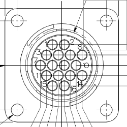
[edit | edit source]The electrical connections to Mr. Stabby are two AMP/TE 206036-1 connectors. These are 16-pin connectors, but they are not entirely populated. There are two connectors, labelled "1" and "2" on the outside of the robot.

| Pin | Function |
|---|---|
| 1 | shoulder top -- goes to shared gnd? |
| 2 | shoulder rotation gnd |
| 3 | CCW shoulder |
| 4 | CW shoulder |
| 5 | Arm full extension endstop |
| 6 | Arm full retract endstop |
| 7 | Endstop wrist CCW |
| 8 | Endstop wrist CW |
| 9 | Endstop Common? |
| 10 | Endstop Common (for wrist) |
| 11 | shoulder bottom t1 |
| 12 | shoulder bottom t2 |
| 13 | Green ground to solenoids |
| 14 | Green ground to solenoids |
| 15 | unpopulated |
| 16 | unpopulated |
| Pin | Function |
|---|---|
| 1 | valve 1 - solenoid 1 |
| 2 | valve 1 - solenoid 2 |
| 3 | unknown (guess: v2s1) |
| 4 | unknown (guess: v2s2) |
| 5 | unknown (guess: v3s1) |
| 6 | unknown (guess: v3s2) |
| 7 | unknown (guess: v4s1) |
| 8 | unknown (guess: v4s2) |
| 9 | unknown (guess: v5s1) |
| 10 | unknown (guess: v5s2) |
| 11 | value 1 - solenoid return |
| 12 | unknown (guess v2 return) |
| 13 | unknown (guess v3 return) |
| 14 | unknown (guess v4 return) |
| 15 | unknown (guess v5 return) |
| 16 | unpopulated |
Wrist endstop connector
[edit | edit source]This is a keyed 3-pin in-line connector located inside the arm housing up top. I'm here numbering the pins 1..3 with 1 being at the oddly shaped end. "Clockwise" and "Counterclockwise" are considered from Mr. Stabby's perspective.
| Pin | Function | Wire color |
|---|---|---|
| 1 | Common | White |
| 2 | CW (clockwise) | Black |
| 3 | CCW (counterclockwise) | Black |
Internal terminal block connections
[edit | edit source]Inside the cylindrical column is a ten-position terminal barrier block. It is isolated behind a plastic shield secured with two screws. In the following table, the connections are labelled from top to bottom, 1 through 10.
| Position | Purpose |
|---|---|
| 1..10 | unknown |
2024 Overhaul
[edit | edit source]Adam is fixing up Mr. Stabby in order to give it away.
| Date | Work |
|---|---|
| February 2024 | Replaced pressure gauges |
| February 2024 | Created cable harness for solenoid valves |
| March 2024 | Created cable harness for endstops |
Resources
[edit | edit source]We're using AQH0223 solid-state relays to control the solenoids. One relay per solenoid. Quick hookup guide: pin 3 to logic ground. pin 2 to logic input; this directly drives an LED with Vf of 1.3V that needs a current of 20mA. You'll need a resistor inline with the input. If your input is 5V, that will be about 180 ohms; for 3.3 volts it will be 100 ohms. Pins 6 and 8 are the output pins; connect these in serial with your circuit. Pin 7 is missing, so you don't accidentally get the relay turned around.
Maintenance procedures
[edit | edit source]Whenever Mr. Stabby is in a state of partial disassembly, it shall be referred to as "Mr. Shambles".